Are you an electronics hobbyist or student venturing out into the fascinating world of embedded system design with 8 bit microcontrollers? GNU/Linux has all the tools required to make this journey fun and exciting. In this month's article, I will take you out an a guided tour of a simple temperature sensor interfacing project I did with an Atmel ATMega8 microcontroller - by the time we finish, you would have acquired all the skills necessary to set up a GNU toolchain based programming environment for the ATMega family.
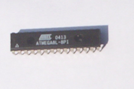
The modern day microcontroller is a sort of `single chip computer'. If you try designing a computer system (say for some control application) using a traditional microprocessor like the 8086, you are likely to abandon the project in frustration very soon. The trouble is that the microprocessor is just one component of the system and you need to add many more (RAM, ROM, timers, counters, interrupt circuitry, I/O ports) to make it complete. This is a non trivial job and requires sophisticated knowledge of processor internals. It's here that the microcontroller comes to our rescue. A mid range 8 bit microcontroller (like the ATMega8) comes packed with all the above mentioned components (plus a few others like Analog Comparators, Serial USART's, Analog to Digital Converters, Watchdog timers) in a single, small footprint, 28 pin package. Often, the only extra component required to make the microcontroller work is a power supply!
The ATMega8 as well as a lot of other microcontrollers from major vendors like Microchip and Atmel comes equipped with a good amount of `flash' memory - non volatile memory which can be erased using electrical signals. The basic idea is to write programs (mostly in assembly language or C) on the PC and convert them to machine code belonging to the target microcontroller's instruction set. Once this is done, the machine code can be transferred to the non-volatile memory of the microcontroller via simple circuits connected to the serial or parallel port. This process is called `programming' or `burning' the micro.
The two factors to be considered when choosing GNU/Linux as your platform for hobby microcontroller based development are:
Copy the following packages from the LFY CD onto a directory (say /usr/local/src) of your GNU/Linux box.
The first step is to compile and install `binutils' (I am assuming that your current directory is /usr/local/src and that all the packages have been extracted to folders under the same directory).
mkdir /usr/local/avr
cd binutils-2.15
mkdir avrobj; cd avrobj
../configure --target=avr --prefix=/usr/local/avr --disable-nls
make; make install
Next, we have to build and install a version of GCC which is capable of generating assembly code for the Atmel AVR and ATMega family of microcontrollers.
export PATH=$PATH:/usr/local/avr/bin
cd gcc-3.4.2
mkdir avrobj; cd avrobj
../configure --target=avr --prefix=/usr/local/avr --disable-nls --enable-language=c
make; make install
We are almost done; only thing remaining is to build the avr C library:
cd avr-libc-1.0.4
export PREFIX=/usr/local/avr
sh ./doconf
./domake
cd build
make install
That's it! We have installed a complete `pure GNU' development environment for our favourite microcontroller.
PC programmers have it easy; once they install a compiler/interpreter for their favourite programming language, they can write a `hello,world' program and have it running instantly. It's not so simple for an embedded system programmer. Compiling the program is just half the job - the other half is downloading the code to the target microcontroller and getting it running. We will do things one step at a time - we will first write a simple C program and convert it to machine code, just to make sure that our newly installed development environment is working fine. We shall then build a simple downloading circuit and use a program called `sp12' to transfer the machine code to the microcontroller.
Here is our test program:
/* a.c, simple test program */
#include <avr/io.h>
main()
{
	uint8_t c = 1;
}
We will compile it as shown below(make sure that /usr/local/avr/bin
is in the path):
avr-gcc -mmcu=atmega8 -Os a.c
Try running the resulting `a.out'. You will get an error message:
./a.out: cannot execute binary file
The reason is that `a.out' contains machine code which will work only on the ATMega8 microcontroller and not on the host PC. This machine code has to be downloaded to the microcontroller using a special program (we will use a very capable tool called `sp12'). But there is one problem. Programs like `sp12' are not capable of deciphering the structure of complex machine code files. The machine code has to be stored in one of two very simple formats - either the Intel Hex format or the Motorola S-record format. Fortunately, a GNU utility called `avr-objcopy' is capable of converting `a.out' into Intel Hex file format which `sp12' is capable of understanding. Here is how you invoke this command:
avr-objcopy -j .text -j .data -O ihex a.out a.hex
Here is part of the resulting Intel Hex format file, `a.hex':
:1000000012C02BC02AC029C028C027C026C025C0C6
:1000100024C023C022C021C020C01FC01EC01DC0DC
The machine code is represented as readable hexadecimal numbers.
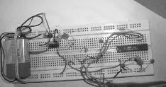
One advantage of using the Atmel AVR or ATMega family is that constructing hardware which helps us download and `burn' code on to the flash memory of the microcontroller is extremely simple. A few resistors, capacitors and an oscillator crystal together with a parallel port connector are all that is required. The complete schematics of the programming board (as well as all the other components/circuits required for completing this project) is available on the LFY CDROM or can be downloaded from http://pramode.net/lfy-feb/. The circuit can be assembled and tested on a breadboard in half an hour (Figure 2 shows the circuit I have built)!
How do you test whether your homebrew hardware is working well? You have to first install a program called `sp12':
tar xvfz sp12v2_1_0-Linux.tgz
cd SP12v2_1.0/Source
make
cp sp12 /usr/local/bin
cp ../_sp12dev /home/pce
The last step of the installation process is copying a file called _sp12dev which is part of the SP12 source distribution to the directory from where you will be invoking the `sp12' command (in this case, `/home/pce').
Now, connect the programming circuit to the parallel port and power it up. Run the command:
sp12 -rFHere is part of the output I got on my machine:
The device code bytes 0,1,2: 0x1e, 0x93, 0x7 were read
from parallel port 0x378 and indicate the following:
You have connected an ATmega8
The device was made by Atmel
We now have a fully functional GNU/Linux environment for programming our microcontroller! Let's try downloading our test program:
sp12 -wpfC a.hexSP12 will display some messages on the console:
Performing chip erase...
Writing content of a.hex into program area.
ooooooooooooooooooooooooooooooooooooooooooooo
a.hex written and verified.
write retries: 0
oooooooooooooooooooooooooooooooooooooooooooooo
Checksum program area: 6b16
The options to SP12 (-wpfC) are simple and intuitive. The `w' stands for a write, `p' says that the write should be to the `program memory' of the microcontroller, `f' indicates the fact that the next argument will be the name of a hex file and `C' is for performing a checksum.
The program which we have just now `burnt' onto the microcontroller doesn't do anything useful. Let's try something more interesting.
Listing 1 shows a program which blinks an LED connected to pin number 28 (the 5th pin of an I/O port called `PORT C') of the ATMega8. Here are a few hints to help you understand the code:
After compiling and transferring the program, we have to put the controller in a simple `running circuit' with an LED connected to pin 28 to see our code in action; the circuit diagram can be obtained from the LFY CD or the URL I had mentioned earlier.
The ATMega8 microcontroller contains some `fuse bits' which can be modified during the program `burning' process. Say you want to run the controller at a higher clock speed of 4MHz using an external crystal; you should set the lower 4 bits of the fuse byte to 1110 without altering the other bits. For this, you have to first read the current value of the fuse bits by running:
sp12 -rFThe `-rF' option stands for `read fuse'. After identifying the controller and printing a few messages (which we have already seen), sp12 displayed the following output on my console:
11100001 are the fuse bits read from an ATmega8
We note that the lower four fuse bits are 0001 - this is the factory programmed value which selects the internal 1MHz oscillator. We will now change it to 1110 to make the controller run on an external crystal in the 3-8MHz range:
sp12 -wF11101110
The project which we are going to do is simple. We will use a cheap and commonly available sensor called `LM35'(Figure 3)
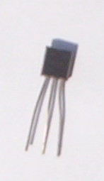
to measure temperature. This sensor converts temperature to voltage - every one degree change in temperature will result in 10mV change in the output voltage. Thus, if the current temperature is 30 degree celsius, the sensor will output 300 milli volts. This analog voltage output is converted to a 10 bit digital value by the built-in Analog to Digital Converter (ADC) of the ATMega8 microcontroller and transmitted to a program running on our Linux system via the serial port. Thus, it becomes essential for us to know how to program the serial port.
Listing 2 shows a C program which keeps on reading data from the serial port. The `init' function programs the UART (Universal Asynchronous Receiver Transmitter, the hardware device which controls the serial port) to accept data at a rate of 9600 bits per second and 8N1 format (8 data bits, no parity, one stop bit).
The UART's base address is 0x3f8. If you want the device to send/receive data at a rate of 9600 bps, you have to write a two-byte `division factor' to 0x3f8 and 0x3f9 after setting the 7th bit of 0x3fb (the `data format register'). The division factor is the number 115200 divided by the desired speed, in this case, 9600; we get the number 12 as a result. After the speed is set, the 7'th bit of the data format register has to be cleared and its two LSB's set to 11 to choose the 8N1 data format.
The 0'th bit of 0x3fd is set when the UART receives a new byte of data over the line. The bit is automatically cleared when the received byte is extracted by reading from 0x3f8.
Isaac Barona has written a Python library called `uspp' which makes serial port programming very easy. Listing 3 is the Python equivalent of the C program in Listing 2. The library can be obtained from http://balder.prohosting.com/ibarona/en/python/uspp/
The ATMega8 incorporates a USART (Universal Synchronous- Asynchronous Receiver Transmitter) using which we can communicate with the PC serial port. Listing 4 is a C program which transmits characters out through the microcontroller's serial port.
The PD1 pin of the microcontroller acts as the transmit pin of the internal USART. The device is initialized by writing a value to the Baud Rate Register, UBRRL and setting the TXEN bit of Control and Status Register B, UCSRB. A value of 25 will set a speed of 9600 bits per second if the external clock being used is 4MHz (It's better to use an external clock when using the serial port because it provides more stable and accurate timing which is essential for correct data transmission). A byte is transmitted out by storing it into the Data Register, UDR. Another byte should be sent only after we make sure that this byte has been fully shifted out; this is done by waiting for the TXC (transmit complete) bit of UCSRA to become 1.
Once the programs for transmitting data (from the microcontroller) and receiving it (on the PC) are ready, we should establish a physical link between the two. The PC serial port, which follows the RS232C signalling standard, defines signal levels of around +12V and -12V for data transmission, and not the usual 0 and +5V. So, the 0 and 5V signals coming out of the microcontroller should be amplified and `level shifted' to around +12 and -12V. Fortunately, there is a very simple (and commonly available) device called MAX232 which performs this translation (schematics on the LFY CDROM).
The ATMega8 comes with a six channel, 10 bit Analog to Digital Converter. The PORTC pins PC0 to PC5 act as the six input channels. The voltage output of the temperature sensor can be fed to any of these channels and digitized. The digital value can then be transmitted to the PC via the serial port. Listing 5 is a program which does exactly this.
The ADC is initialized by choosing channel 0 (write 0 to the ADMUX register) and setting the ADEN bit (as well as two other bits) of the register ADCSRA. The process of digitizing the analog input on the chosen channel is triggered by setting the `start-conversion-bit' (ADSC) of ADCSRA. The ADIF bit is set when the conversion is over. The lower 8 bits of the digital output is available in ADCL - the other two bits are available as the least significant bits of ADCH. The program shown in Listing 5 simply initializes the ADC and USART, sends a start-of-conversion signal, waits for the conversion to be over and then reads the digital output and transmits it via the USART as two independent bytes. This is done in an endless loop.
Unix-like operating systems have been traditionally very strong in processing textual data. The Unix shell, with its facilities for redirection and piping together with myriads of tools for extracting information from text files (grep, sed, awk, Perl), plotting graphs (Gnuplot) and performing mathematical analysis (Scilab, Octave, Numerical Python) makes the GNU/Linux environment an ideal platform for conducting interfacing experiments, gathering data and analysing them scientifically. As a simple example, suppose you wish to quickly scan the data which the microcontroller is sending over the serial port and count the number of occurrences of a byte say 67. You write a simple script called `howmany':
#!/bin/sh
cat $2|grep "^$1$"|wc -l
and run it like this:
./howmany 67 logwhere `log' is a file which contains data read from the serial port; this file itself has been created by running:
./a.out > logwhere `a.out' is a program which reads a certain number of bytes from the serial port and simply displays it on the screen. Now, you become a bit more ambitious and want to tabulate the number of occurrences of every number from 0 to 255:
#!/bin/sh
start_val=0
end_val=255
while [ $start_val -le $end_val ]
do
    echo $start_val '------->'  `./howmany $start_val $1`
    start_val=`expr $start_val '+' 1`
done
The amazing thing here is the ease with which you are able to automate the data processing tasks. Try doing it on any other operating system!
Developing microcontroller applications (and in general, all kinds of hardware interfacing projects) with GNU/Linux is lots of fun and a great learning experience. To exploit the full power of the platform, you should be familiar with the `Unix Philosophy' originally expounded by Kernighan and Pike in their classic `The Unix Programming Environment' and later by Eric Raymond in `The Art of Unix Programming' (available in full at http://www.catb.org/~esr/writings/taoup/).
Serial port programming at the hardware level is examined in depth at http://www.beyondlogic.org/serial/serial.htm. The system call level interface to the serial port is examined in detail in a document available at http://www.easysw.com/~mike/serial/. The LM35 datasheet can be downloaded from http://www.national.com/pf/LM/LM35.html and the ATMega8 microcontroller programming manual from http://www.atmel.com/dyn/resources/prod_documents/doc2486.pdf. An article on ATMega8 programming with GNU/Linux is available in the November 2004 issue of the online magazine, LinuxFocus (http://www.linuxfocus.org).