Welcome to the exciting world of Free and Open Source Software based FPGA programming!
Introduction
FPGA programming has long been the domain of proprietary tools. In order to get a simple LED blinking design up and running, you will have to download a few gigabytes of tools from the website of companies like Altera or Xilinx, the two major players in the field. Free Software implementations of Verilog and VHDL (the two most important hardware description languages) are available; but these are useful for simulation purpose only. If you want to get your design up and running on real hardware, you will have to generate a bitstream to configure the logic blocks within the FPGA; this can only be done by proprietary tools. It is as if a microprocessor manufacturer gave you a chip and did not provide any information about its instruction set architecture and encoding.
Project IceStorm
The IceStorm project, one of the most ambitious Free Software projects I have seen in recent years, plans to change all that. This project has reverse engineered and documented the bitstream format of Lattice Semiconductor’s Ice40 family of FPGA’s. They have also developed a completely free software toolchain which will take you from Verilog code to its actual realization on an ICE40 FPGA. The availability of this toolchain has generated a lot of excitement among hardware hackers and FOSS enthusiasts.
ICE40 based development boards
This article describes how you can implement your digital designs (coded in Python) on an IcoBoard. There are a few other development boards supported by the IceStorm tools:
We can expect to see a lot more boards getting released in the coming months.
IcoBoard tool setup
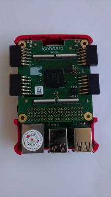
The IcoBoard is a Raspberry Pi add-on board. Here is a photo of the board attached to my Raspberry Pi 3.
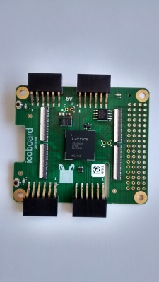
And here is the stand-alone board:
We will do all the development on the raspberry pi - from writing Python code to uploading the bitstream to the icoboard.
Follow the instructions given here to install all the required tools; you might skip the sections “Building and running a simple example” and “Building and running a complex SoC Design”.
Note that most of these tools are downloaded as source and compiled on the Raspberry Pi; compiling some of the tools will be a slow process as the tools are complex and the Rpi is not as fast as a modern PC/Laptop.
Install Migen
We will use Python as our hardware description language. If you do some research on the net, you will see that people mostly recommend two Python frameworks:
As a total newbie (to the field of FPGA programming), I found Migen to be the easier of the two.
Installing Migen is simple: clone the repository and set the PYTHONPATH environment variable to point to the folder corresponding to the cloned repository.
git clone https://github.com/m-labs/migen

export PYTHONPATH=`pwd`/migen
You can get the Migen tutorial from here. Also check out this documentation page.
Hello, World!
Let’s now write some code which will put on an LED on the IcoBoard.
from migen import  *
from migen.fhdl import verilog

m = Module()
led1 = Signal()

m.comb += led1.eq(1)

print(verilog.convert(m, ios={led1}))
This Python code will be converted to Verilog; the IceStorm tools will then generate a bitstream (after several stages of processing) and the bitstream gets written to the FPGA - this will result in one of the on-board led’s going HIGH.
A signal is a fundamental building block in any Migen design; you can visualize it is a piece of wire or a 1-bit register. Here, we are creating a signal called led1 by writing:
led1 = Signal()
A module is another fundamental building block. A digital module may contain a lot of combinational and sequential circuits.
Let’s first look at what this line does:
led1.eq(1)
You can reason about it at two levels. At the level of the logic circuit, this is a combinational statement which connects the wire led1 to logic HIGH.
At the level of the Python program, led1.eq(1) creates an “Assign” object which has two attributes, l and r; l refers to the object on the left hand side of the assignment and r indicates the object on the right hand side of the assignment. Here is what you get when you do some interaction at the Python prompt:
>>> p=led1.eq(1)
>>> p.l
<Signal led1 at 0x769c07b0>
>>> p.r
<migen.fhdl.structure.Constant object at 0x769c08d0>
>>> p
<migen.fhdl.structure._Assign object at 0x769c0950>
>>>
So what does the following statement do?
m.comb += led1.eq(1)
The module object has a special attribute called comb, we can visualize this attribute as referring to a sequence of combinational statements. We are adding the “Assign” object returned by the following statement:
led1.eq(1)
to this list of combinational statements.
Now comes the statement which generates Verilog:
print(verilog.convert(m, ios={led1}))
The convert function iterates through each element of m.comb generating equivalent Verilog code; the set represented by ios is a set of signals which are the input/outputs of the module m.
Here is the verilog output produced by the above program (note: use Python3 to run the program):
/* Machine-generated using Migen */
module top(
        output led1
);


// synthesis translate_off
reg dummy_s;
initial dummy_s <= 1'd0;
// synthesis translate_on
assign led1 = 1'd1;

endmodule
Logic synthesis using yosys
As the first step of our design process, we wrote the code in Python and converted it into Verilog:
python3 t1.py > t1.v
(assume t1.py is the name of the source file containing Python code; t1.v contains Verilog source)
The next step is logic synthesis; the idea is to convert the high-level specification provided by the Verilog program into a sequence of inter-connected logic gates. We will do synthesis using Yosys.
yosys -p "synth_ice40 -blif t1.blif" t1.v
The synthesized output is stored in a file called t1.blif.
[Note: here is some documentation regarding the blif format]
Place and route
Now we come to the device-dependent part of FPGA programming.
The blif file produced by the synthesis phase contains a description of our circuit in terms of logic elements; we need to take this description and turn it into instructions regarding exactly what all logic blocks of the FPGA are to be used and how they have to be interconnected. We will do this using arachne-pnr
arachne-pnr -d 8k -p t1.pcf -o t1.txt t1.blif
What is the role of the file t1.pcf? What does it contain?
Let’s find out. Here is what I see when I do a “cat t1.pcf”:
set_io led1 C8
Each pin of the FPGA is identified by a specific label; the pin to which one of the onboard LED’s is connected has the label C8. The .pcf file basically maps the name led1 (which we are using in our Python/Verilog code) to its internal label.
Here is another example of a pcf file:
set_io sys_clk R9
set_io led1 C8
set_io led2 F7
set_io led3 K9
Ok, so “arachne-pnr” gives us a textual “bitstream” in a file called t1.txt. We are almost done!
Packing the text bitstream
The next step is to convert the textual bitstream to binary form using a tool called icepack:
icepack t1.txt t1.bin
Configuring the FPGA with the bitstream
Finally, we are ready to configure the FPGA with our binary bitstream; we use a tool called icoprog for this purpose:
sudo icoprog -p < t1.bin
That’s it! You will see that one of the on-board LED’s of the IcoBoard is ON!
A simple shell script
Let’s now write a tiny shell script which will do all the steps mentioned above, taking the Python program as the input (a makefile would of course be better):
python3 $1.py > $1.v
yosys -p "synth_ice40 -blif $1.blif" $1.v
arachne-pnr -d 8k -p $1.pcf -o $1.txt $1.blif
icepack $1.txt $1.bin
sudo icoprog -p < $1.bin
As an exercise, you can try writing a Python program which will put on ALL the 3 onboard LED’s of the IcoBoard! (note: don’t forget to use a .pcf file with proper pin definitions).
Blinking LED!
The ICE40 FPGA on the IcoBoard is clocked at 100MHz (I believe … please correct me if I am mistaken).
We will write some code which will blink one of the onboard LED’s at a rate of a few Hz; so we need to scale down the clock.
Let’s say we have a 3 bit counter whose value gets incremented once
for each rising edge of the clock (assume clock
frequency is N Hz). Here is the pattern:
0 0 0
0 0 1
0 1 0
0 1 1
1 0 0
1 0 1
1 1 0
1 1 1
The least significant bits of the pattern will be 0 for one full clock cycle, 1 for the next cycle, and so on. So the frequency is N/2. The next bit (bit D1) varies in this manner: 0,0,1,1,0,0,1,1, which gives a frequency of N/4 and so on…
Here is the Python code:
from migen import  *
from migen.fhdl import verilog

m = Module()
counter = Signal(24)
led1 = Signal()

m.comb += led1.eq(counter[23])
m.sync += counter.eq(counter+1)

print(verilog.convert(m, ios={led1}))
The statement:
Signal(24)
creates a 24 bit wide register. We are then assigning the value of the 23rd bit (MSB) to the LED. The frequency with which this bit varies will be:
100000000.0/(2 raised to 24)

= around 6Hz
We are now building a clock-driven circuit; the statement:
m.sync += counter.eq(counter + 1)
results in the counter getting incremented every clock cycle.
The .sync attribute is a collection of operations to be executed each clock cycle. During the Verilog code generation phase, Migen will walk through the elements of both the .comb and .sync attributes and generates equivalent Verilog statements.
Here is the verilog code produced by Migen:
/* Machine-generated using Migen */
module top(
        output led1,
        input sys_clk,
        input sys_rst
);

reg [23:0] counter = 1'd0;

// synthesis translate_off
reg dummy_s;
initial dummy_s <= 1'd0;
// synthesis translate_on
assign led1 = counter[23];

always @(posedge sys_clk) begin
        if (sys_rst) begin
                counter <= 1'd0;
        end else begin
                counter <= (counter + 1'd1);
        end
end

endmodule
The .pcf file should contain a mapping for sys_clk:
set_io sys_clk R9
set_io led1 C8
As an exercise, you can try writing a program which will blink two LED’s at two different rates.
Conclusion
We have seen how easy it is to get started with FPGA programming usig Python and the free software tools created by the IceStorm project. So what are you waiting for, get yourself an IcoBoard (or something similar based on ICE40 FPGA’s) and start experimenting!